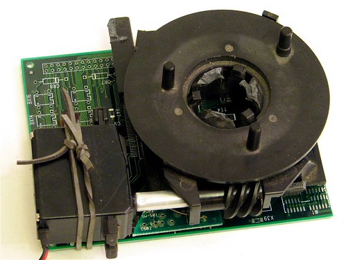
The compressor on an Atlas Copco XAS 186 suddenly starts running hot. The operator notices the engine is fine, the compressor pressure is low, and there’s an unusual smell from the coupling housing. When the technician opens the housing, the rubber coupling element — a six-pointed star-shaped spider — has disintegrated. Fragments are distributed throughout the housing. The metal coupling hubs have been running in contact for an unknown period.
The coupling element cost $45. The damage assessment: $3,200 in coupling hub replacement, $800 in labor, and a two-week wait for a specialist to rebore the hub bores that had worn out of round.
Rubber coupling elements are the mechanical fuse in power transmission systems. When everything is working correctly, nobody thinks about them. When they fail, they fail in ways that are disproportionately expensive relative to their cost. This guide covers how to select the right coupling element, how to identify early failure, and what specifications matter for drill, compressor, pump, and industrial applications.
How Rubber Coupling Elements Work
A flexible coupling connects two rotating shafts while accommodating small misalignment between them. The rubber element (also called the coupling insert, coupling spider, or coupling element) is the compliant member that makes this possible.
There are two fundamental designs:
Jaw Couplings (Claw Couplings)
Two metal hubs with interlocking jaws (usually 3 or 6 jaws per hub). A rubber spider element sits between the hubs, with each arm of the spider fitting between opposing jaws. The rubber transmits torque through compression of the spider arms against the jaw faces.
In normal operation, the spider arms are in compression — rubber works well in compression. Failure modes:
– Compression fatigue: Repeated compression-release cycles eventually cause the rubber to crack at the arm root
– Overload crushing: Shock loads compress the rubber beyond its elastic limit, causing permanent deformation and reduced stiffness
– Aging: Heat, oil contamination, and ozone degrade the rubber compound over time regardless of load
Elastic (Disc) Couplings
A ring or disc of rubber or polyurethane bonded between two flanges. The rubber works in shear rather than compression. Advantages: lower radial stiffness (better misalignment accommodation), more predictable failure mode (the disc cracks radially rather than disintegrating). Common on European industrial equipment.
Tyre (Donut) Couplings
A toroidal rubber element that fits over two flanged hubs. Very soft radially — excellent at absorbing shock and misalignment. Common on large compressors, generators, and drill rigs. Higher torque capacity than jaw couplings of similar outer diameter.
Applications by Industry
Drilling Equipment (Atlas Copco, Furukawa, Ingersoll Rand)
Rock drills and crawler drills use rubber couplings at two locations:
1. Engine to compressor: Large tyre or disc coupling, high torque, high shock loading from compressor pressure pulses
2. Compressor to drill motor: Smaller jaw coupling or disc coupling
Atlas Copco specifies coupling elements by machine model and serial number. Key series:
– XAS/XAVS portable compressors: jaw coupling elements, typically polyurethane spider for longer life in high-temperature engine compartments
– CPS series: disc coupling elements
– Boomer and Simba drill rigs: tyre coupling elements on the main drive
Polyurethane coupling elements typically last 2–3x longer than standard rubber in high-temperature applications (above 60°C continuous). The tradeoff: polyurethane is less effective at absorbing high-amplitude shock loads. For applications with frequent high-shock events (drilling hard rock, for example), a softer rubber compound may be preferable despite shorter life.
Construction Equipment Pump Drives
Excavator main hydraulic pumps are typically driven through a rubber coupling from the engine flywheel. The coupling must:
– Transmit full engine torque (250–600 Nm on large machines)
– Absorb the pressure-pulse vibration from the piston pump
– Accommodate angular misalignment between the engine and pump
These couplings see extremely high cycle counts — at 1,800 RPM engine speed, a coupling element completes 1,800 torque cycles per minute, 108,000 per hour, over 600 million in a 6,000-hour service life. Fatigue life of the rubber compound is the primary selection criterion.
Industrial Pumps and Compressors
Industrial applications tend to be more predictable in load profile than mobile equipment — consistent torque, predictable temperature, controlled environment. Standard rubber compound (natural rubber or NBR) coupling elements are typically adequate.
Selection criteria for industrial applications:
– Torque rating: Must exceed maximum system torque with a safety factor of 1.5–2.0
– Bore and keyway dimensions: Must match shaft specifications exactly
– Hardness: Softer elements (Shore A 60–75) for smoother torque transmission; harder elements (Shore A 85–98) for more precise shaft positioning
Selecting the Right Rubber Compound
Not all coupling elements that look identical perform identically. The rubber compound determines:
| Property | Natural Rubber | NBR (Nitrile) | Polyurethane |
|---|---|---|---|
| Temperature range | -40°C to +80°C | -30°C to +100°C | -30°C to +120°C |
| Oil resistance | Poor | Excellent | Good |
| Dynamic damping | Excellent | Good | Fair |
| Fatigue life | Good | Good | Excellent |
| Shock absorption | Excellent | Good | Fair |
| Cost | Low | Medium | High |
For drill and compressor applications (high temperature, possible oil contamination): NBR or polyurethane
For hydraulic pump drives (high shock, moderate temperature): Natural rubber or NBR
For industrial drives (controlled environment): Natural rubber standard
Failure Identification and Inspection
Visual Inspection
Remove the coupling guard and inspect with the machine stopped and locked out:
- Cracks: Radial cracks in spider arms or disc elements are normal aging. Cracks penetrating more than 50% through the element thickness require replacement.
- Permanent deformation: Spider arms that are visibly flattened or twisted indicate overload history. Replace and investigate the cause.
- Fragmentation: Any missing material means the element has already failed in service. Inspect the coupling bores for metal contact damage before installing replacement.
- Oil saturation: Rubber that is swollen, soft, and glistening has been contaminated with oil. Oil-contaminated rubber cannot be restored — replace and fix the oil leak source.
Performance Indicators
- Torsional vibration: A worn coupling element has reduced damping capacity, allowing more torsional vibration to transmit between shafts. Often felt as a change in machine noise signature.
- Increasing shaft misalignment: A worn coupling allows more relative shaft movement, which can be measured with a dial indicator.
- Coupling housing temperature: A coupling running with contact metal-to-metal will generate heat. An infrared thermometer on the coupling housing during operation can identify this before visual inspection.
Inspection Interval
For most applications: inspect coupling elements at every 500-hour service. On high-shock applications (rock drills, compactors): every 250 hours.
Replacement and Installation
Measure Before Ordering
Before ordering replacement coupling elements, measure:
1. Spider arm width and length (for jaw coupling spiders)
2. Outer diameter of the spider or disc
3. Number of spider arms or disc slots
4. Shore hardness of the original element (if still intact)
These measurements allow cross-referencing to the correct element even if the OEM part number is not available.
Installation Points
- Do not lubricate: Rubber coupling elements should be installed dry. Lubricating the spider arms changes their friction behavior against the jaw faces, altering torsional stiffness.
- Check hub condition: Jaw faces should be sharp-edged, not rounded. Rounded jaws from metal contact during element failure will cause premature wear on the replacement element. Regrind or replace worn hubs.
- Verify alignment: A rubber coupling can accommodate misalignment, but it should not be used to correct misalignment. Angular misalignment over 1° significantly shortens element life. Align shafts to within 0.3° before relying on the coupling element for remaining accommodation.
Babacan Group Coupling Elements
Babacan Group manufactures rubber coupling elements for drill equipment, industrial drives, and construction equipment pump applications. Our coupling range covers:
- Jaw coupling spider elements (natural rubber, NBR, polyurethane) in standard and custom sizes
- Tyre/donut coupling elements for large compressor and drill applications
- Disc coupling elements for industrial and European equipment applications
- Atlas Copco, Furukawa, Ingersoll Rand drill equipment coupling cross-references
All coupling elements are manufactured with documented hardness specifications and compound references traceable to material test records. ISO 9001:2015 certified production, worldwide shipping.
For cross-references on Atlas Copco or other drill equipment coupling elements, or for industrial coupling specifications, contact our technical team or submit a quote request.
Key Takeaways
-
Rubber coupling elements are a system protection device — they fail to protect the connected equipment. When an element fails, inspect the coupling hubs for damage before installing a replacement.
-
Compound selection determines service life: Polyurethane for high-temperature applications, natural rubber for best shock absorption, NBR for oil-contaminated environments.
-
Hardness matters: Softer elements damp more, harder elements position shafts more precisely. Match hardness to application.
-
Measure before ordering if you don’t have the part number: Spider arm width, outer diameter, arm count, and approximate hardness are enough to cross-reference a replacement.
-
Alignment is not the coupling’s job: Fix misalignment before installing a new element. Using the coupling to compensate for misalignment cuts element life by 50–80%.
Browse our coupling element catalog or contact Babacan Group with your equipment model for a direct specification.
Word Count: ~1,450 words